JUMO dTRANS Rw 01
Table of content
What is to be taken into account for ultra-pure water measurement?
Measurement and calibration must be carried out in a closed measuring circuit or in a closed container.
Any contact of the medium to be measured with the atmosphere results in a notable change of its conductivity.
For this, we recommend to use a measuring cell with ASTM inspection certificate.
An 'ERR' error message appears on the device.
Calibration of the relative cell constant or determination of the temperature coefficient of the medium to be measured was completed with an error. The previous data is saved.
The factory data is displayed (Cell = 100%, ALPH= 2.3).
To remedy the 'ERR' error message, manually change the two parameters using the keyboard (e.g. change by one digit up or down and confirm with the PGM key) or re-calibrate the system.
An actual value output is required - What is to be taken into account?
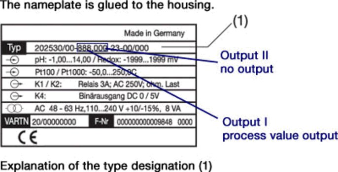
Ensure that the device is equipped with the respective analog output. For this purpose, check the type designation of the device.
Refer to chapter 4.1, Type explanation, in the operating instructions.

Configuration level C213 - Other outputs I is set.
Actual value output 2 is set in configuration level C214 - Other outputs II.
The scaling is set under the parameters SOL and SOH.
I cannot change settings in the parameter level and the configuration level.
To be able to carry out settings in the two levels, enter the respective CODE for activation first.
Start situation > Measuring mode > Repeatedly press the PGM key until CODE appears. Set the respective CODE by pressing the UP/DOWN keys. Press the PGM key to confirm.
The display returns to 0000. Now, the corresponding level (parameter) can be selected. The code has been entered correctly when the decimal point flashes during entry.
| Function | Code |
| Unlock the operator level, CAL and manual activation of Hold. | 0110 |
| Unlock the operator and parameter level. | 0220 |
| Unlock all levels. | 0300 |
Is it possible to change the switching behavior of N/C / N/O?
The setting N/O / N/C for the two contacts K1 and K2 can be changed in the configuration level under point C212 (controller outputs).
Both contacts are factory set to NOC.
NOC: (N/O) The corresponding output is active (closed) as long as the switching condition is fulfilled.
NCC: (N/C) The corresponding output is active (closed) as long as the switching condition is not fulfilled.
What does Min/Max contact mean?
The configuration level C212 (controller outputs) can be used to change the Min/Max behavior for the two contacts K1 and K2.
MIN contact: The switching condition is fulfilled when the actual value is lower than the set point value.
MAX contact: The switching condition is fulfilled when the actual value exceeds the set point value.

How to check the correct function (actual value display) of the device and the coax cable?
The Redox value can also be preset with a pH simulator as for the pH measurement. Then the Redox value can be read from a table contained in the simulator operating instructions. If the simulator is not available, it is possible to directly supply voltage to the device input (BNC socket) and, to check the coax cable, to the end of the cable.
The Rd value can be read on the device according to the voltage.
The device should have the factory settings and should not display any error messages.
| pH value | Voltage |
| 2 pH | +295,8 mV |
| 4 pH | +177,48 mV |
| 7 pH | 0 mV |
| 10 pH | -177,48 mV |
| 10 pH | -295,8 mV |

How to start the calibration process?
To be able to start calibration, activate the controller.
Start situation > Measuring mode > Repeatedly press the PGM key until CODE appears > Enter 0300 and confirm with PGM > Press the Exit key once > Simultaneously press the PGM + Down key.
A temperature of 25.0 appears in the top (red) display, °C appears in the bottom (green) display, the decimal point in the bottom display flashes.
- ${title}${badge}


